Support family coding workshops in Gloucestershire: paypal.me/cotswoldjam
If you have a Raspberry Pi (or more specifically, Raspbian x86 Pixel desktop) as a virtual machine on your Windows/Mac/Ubuntu PC/laptop, you can attach a real Raspberry Pi Zero and use its GPIO pins to control basic operations such as flashing an LED or detecting button presses.
Note that this can NOT yet be used for more advanced SPI/I2C add-ons such as HATs or Blinkt etc. It's just basic on/off/PWM output and high/low input. Great for breadboard projects with components such as LEDs, buttons, resistors etc. Some very simple add-ons such as traffic light LEDs, basic H-bridge motor controllers or charlieplexed Christmas LEDs may also work.
You will need:
This tutorial assumes you are using an existing, working installation of VirtualBox as the virtual machine host, and Raspbian x86 as the virtual guest; see my setup how-to.
Don't connect your real Pi Zero yet. Boot up your virtual Pi and make sure it is up-to-date. From the terminal:
sudo apt update
sudo apt -y upgrade
Now install the USB boot device handler:
sudo apt install usbbootgui
(it may say that usbbootgui is already the newest version - that's fine)
Shut down your virtual Pi:
sudo shutdown -h now
Remove any SD card from the Pi Zero.
Connect your real-world Pi Zero's USB port (the middle port - not the power port) to a micro USB cable. Make sure it is a proper micro USB data cable, not just a charge-only cable. I recommend a short, high-quality cable (look for an AWG value of 24 or lower - which means thicker) and I also recommend that you do NOT use a USB hub (connect directly to your PC/laptop).
From the Virtualbox host window, select your virtual Pi then click the Settings button.
Select USB and then click the plug + icon.
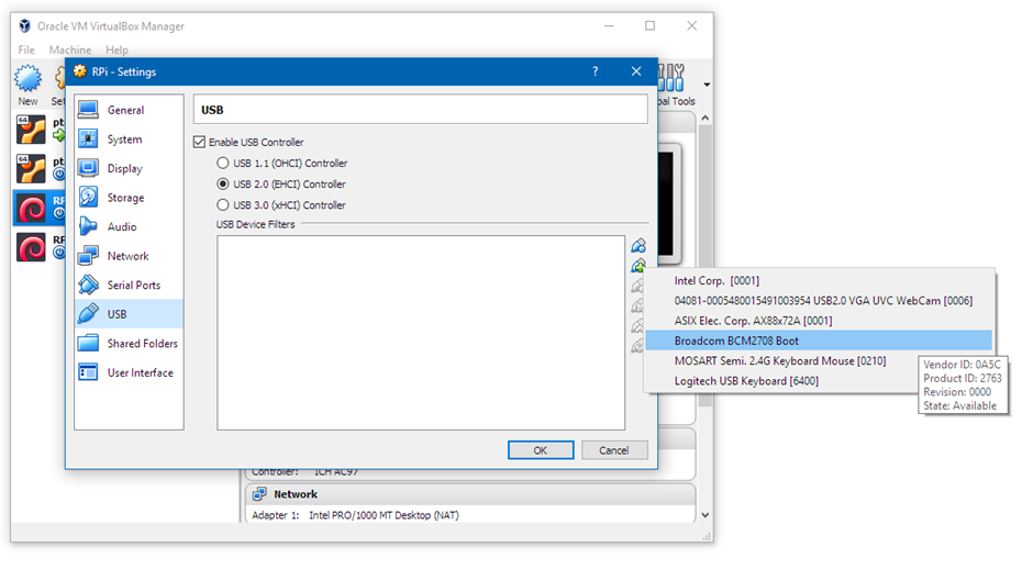
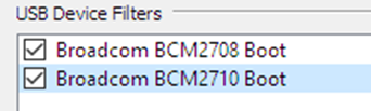
Select "Broadcom BCM2708 Boot".
"Broadcom BCM2708 Boot " should now appear on the list. Click OK. (Can't see this entry? You did remove the SD card from the Pi Zero, right?)
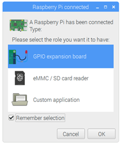
Start the virtual machine. Once booted, it should show a new window saying "A Raspberry Pi has been connected."
Select that you want to use it as a "GPIO expansion board", tick "Remember selection" and click OK.
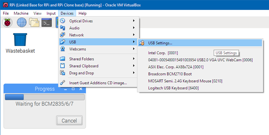
It will display a progress bar. After a moment, it will hang at "Waiting for BCM2835/6/7".
This is where things start to get complicated. The Pi Zero becomes three different USB devices, depending on how far through the USB boot process you are (technically it's booting over IPv6 network), and we need to tell the host to let the virtual Pi control all of them. So far, we've only told the host about one of those three.
Note that you don't want to take too long doing the following steps. The "Raspberry Pi connected" wizard will time out if you take too long. If that happens, just unplug the real Pi and start again.
Go into the host Devices - USB - USB Settings menu.
Now click the Plug Add icon and add "Broadcom BCM2710 Boot".
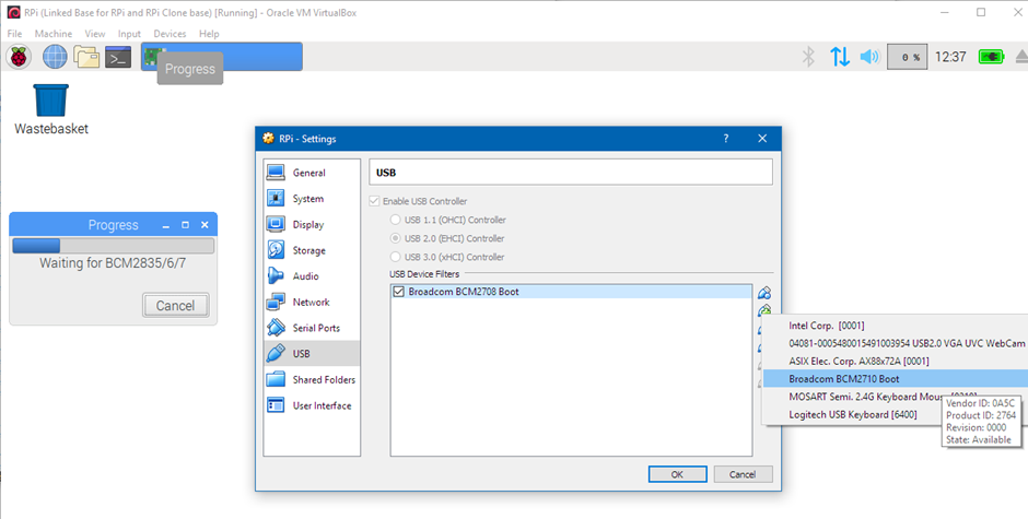
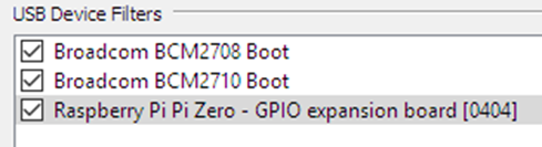
You should now have two Broadcom devices listed:
Click OK. The progress will continue, then the window will close.
Now, again from the Devices - USB menu, click the Plug Add button and select "Raspberry Pi Zero - GPIO expansion board"
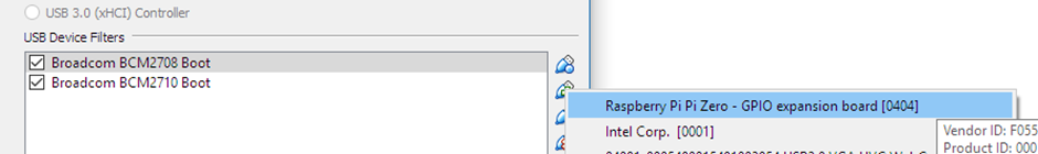
This will now give you three devices:
The reason we're doing this through the "USB Settings" menu, and not directly from the Device - USB menu, is that if you do it through "USB Settings", it remembers it after reboot.
Note that if you take a long time to add the extra devices, the process may not work - it gives up after a while. Just unplug the Pi Zero and start again. You don't need to be super fast, but you don't want to hang about making the selections. That's why we're making sure that these settings survive a reboot; we don't want to have to go through this effort every time.
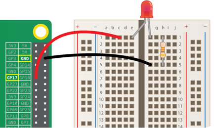
You can now control GPIO pins using GPIOZero. Suppose you have an LED & resistor connected to ground and GPIO 17:
Then, from a terminal:
export GPIOZERO_PIN_FACTORY=pigpio
export PIGPIO_ADDR=fe80::1%usb0
python3
>>> from gpiozero import LED
>>> led = LED(17)
>>> led.blink()
All the basic GPIOZero input device and output device functions such as button, PWMLED etc. seemed to work for me. I don't expect SPI devices nor advanced boards & accessories to work. If you're going to be doing this a lot, you can add the export lines to your ~/.profile :
echo -e "\nexport GPIOZERO_PIN_FACTORY=pigpio\nexport PIGPIO_ADDR=fe80::1%usb0\n" >> ~/.profile
Reboot the virtual machine to ensure this change is applied.
shutdown -r now
You can check the Pi Zero's connection with:
ping6 -c 5 fe80::1%usb0
Problems? Try a better quality, shorter micro USB cable. If you're using a USB hub, try directly attaching the Pi Zero to your PC/laptop instead. Also bear in mind that this really only works for basic breadboarding - LEDs, switches, resistors etc. - and won't work for advanced HATs or add-ons such as Blinkt, Sense HAT etc. (IC2, SPI etc). Some very simple add-ons such as Pibrella or simple H-bridge motor controllers or Christmas tree LED arrays may work.
Another gotcha for problem-solving, is that you must remove the SD card from the Pi Zero in order for it to boot over USB.
The Raspberry Pi Foundation has more details including usage with Scratch 2.
If you found this article useful, please make a donation - however small - to Cotswold Jam, the family-friendly coding & electronics club that I run in Gloucestershire. We run entirely on donations, we don't claim tax relief nor taxpayer-funded grants, and in addition to running four workshops for 60 children five times a year, we try to give away GPIO electronics kits. All cards are accepted and you don't need a PayPal account. paypal.me/cotswoldjam
Comments, errors and corrections to: andrew@aoakley.com
Public Domain - Andrew Oakley - 2018-06-26