This is part 2 of a 3-part series on building a Lego robot which can be controlled by a Raspberry Pi. Previously in part 1, I showed the Lego build, including tracks, gearboxes, motors, chasis, battery box holder, breadboard holder and how to mount the Raspberry Pi onto the Lego.
On other pages:
 An electronics breadboard - strictly speaking, a solderless breadboard - is a wonderful, wonderful thing that lets you wire up circuits without any soldering required. Since there's no soldering, you can try stuff out, remove and re-insert wires into different holes, you can make mistakes and, most of the time, cause no damage. There are a few ways you might burn out components, but the components themselves are usually cheap, in the order of pennies or at most three pounds. There's a reason why you can buy a cheap MP3 player for five quid; basic mass-produced electronic components cost next to nothing. It's only when you want a display, a touchscreen or a special kind of sensor like GPS that things get expensive, and no doubt by 2020 they'll be knocking those out for under a quid, too. The microchip we're going to use, the L293D chip, has diodes (the D at the end of the name), which prevent electricity flowing through it the wrong way, so your chances of burning out something by making a mistake with this particular circuit are pretty low.
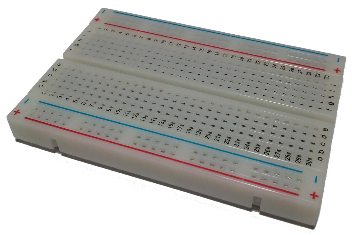
 With a breadboard, you have two long horizontal sets of holes at the top and bottom of the board. Each of these horizontal rows are connected together; plug a live cable into one hole, and all the other holes on that row are live. These long horizontal rows usually have a red and blue line next to them, and are often used to carry positive and negative from the batteries or power supply.
In the middle of the board are two panels of pins arranged in columns of five; each column of these are connected. There is a centre channel which separates the upper from the lower columns. So if you plug a live cable into one pin on a column of five, all other pins on that column of five become live.
Almost all electronics components have a standard size, such that each connector is in multiples of 2.54mm apart (a strange number, but it originated in the USA where they still use a variant of the Imperial system; 2.54mm is one-tenth of an inch). The holes on the breadboard match up; they're all 2.54mm apart too. Also, most microchips are exactly the width of the central channel running along the middle of the board, so you can plonk a microchip across the middle of the board, and have each of the chip's legs dangling into one vertical column of five holes.
Breadboards are introduced much better by John Hewes over on Electronics Club so I'm not going to explain much further here. Sparkfun also have a longer introduction to breadboards which includes some history and a simpler getting-started project.
You can either wire up your breadboard directly to your Raspberry Pi, using male-to-female jumper wires, or you can use male-to-male jumper wires plus something like the Adafruit Pi Cobbler to connect to a ribbon cable.
A picture is worth a thousand words, so let's get straight to the point:


Microchips have a little semicircle cut into them which let you know which is the "top" or "left" of the chip. This is important, because the legs (called "pins") are numbered, and the numbering starts from just underneath the semicircle, if the semicircle is on the left. Numbering runs anti-clockwise.
Place the L293D microchip onto the breadboard so that it sits straddling the centre channel. Then wire up the microchip's pins as follows:
| L293D pin | Connect to BCM pin |
Purpose | 1 | 22 | Right motor enable | 2 | 17 | Right backward input | 3 | (none) | Right motor negative | 4 | (none) | Motor batteries negative | 5 | (none) | Motor batteries negative | 6 | (none) | Right motor positive | 7 | 4 | Right forward input | 8 | (none) | Motor batteries positive |
|---|
| L293D pin | Connect to BCM pin |
Purpose | 16 | 2 | Raspberry Pi 5v | 15 | 24 | Left backward input | 14 | (none) | Left motor negative | 13 | (none) | Motor batteries negative | 12 | (none) | Motor batteries negative | 11 | (none) | Left motor positive | 10 | 25 | Left forward input | 9 | 22 | Left motor enable |
|---|
You'll note that both L293D pins 1 and 9 connect to BCM pin 22. That's because I decided to have one single BCM pin to enable to disable both motors. I just used a jumper wire to connect L293D pin 1 to pin 9, and then connected pin 1 to BCM pin 22. However you could quite easily have separate BCM pins for each if you wanted.
BCM numbering is a bit "fun", if by "fun" you mean slightly complicated but for an interesting reason. BCM is an abbreviation for Broadcom, who make the main combined processor and graphics chip on the Raspberry Pi. The processor has no idea about the actual layout of pins on it's circuit board, so unfortunately the numbers we use in programs to refer to electrical pins, bear no relation to the layout of the GPIO connector.
 To make things even more "fun", the GPIO pins on the Raspberry Pi are numbered in a different sequence to the L293D microchip. The L293D microchip's pins are numbered anti-clockwise, but the Raspberry Pi's GPIO pins are numbered bottom-to-top, left-to-right in pairs. Don't think about it, just look at the diagram.
Pin 13 has two possible BCM numbers. If you have a revision 1 Raspberry Pi, then it has BCM number 21. If you have a revision 2, it's 27. So, how can you tell the difference? Revision 1 boards have no mounting holes and the audio connector is black. Revision 2 boards have a mounting hole directly under the raspberry logo, and they also have a blue audio connector. More details on Raspberry Pi revisions at Raspberry Pi Spy. To be honest, since I own several Raspberry Pis including both revisions, I just avoid using pin 13.
You'll note we're not using the Raspberry Pi's ground pin. We'll use the ground (negative) from the motor batteries instead.
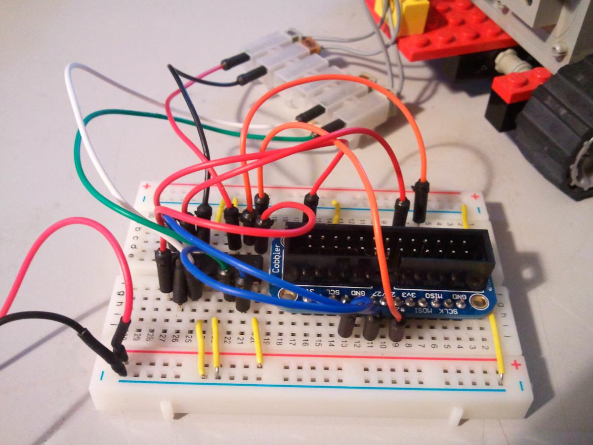
Here's some photos of my breadboard. I'm heavily colour-blind, so excuse me if the wire colours don't match my own diagrams. Trust the diagrams, not the photos.

Speech and a speaker is optional.
It's easy to make the Raspberry Pi talk, using any of a number of free Linux speech synthesis programs. What you will need, from a hardware perspective, is a powered speaker. The Pi's audio socket only outputs at a very quiet level, barely suitable for headphones, so you will need speakers that get their power from somewhere else. Since the robot moves about, you need that to be batteries rather than the mains. I used the iLuv i209 micro portable speaker which takes one AA battery (I try to stick with AA batteries since I have a huge stash of rechargable ones), but there are also rechargable "hamburger" speakers and lots of other choices. Just make sure it's small and light enough not to capsize the robot.
If you're using a Model B Raspberry Pi with two USB ports, I don't recommend using the spare USB port for speaker power, as this will drain the Raspberry Pi's batteries pretty fast, and your Pi may not have sufficient amps to run properly.
A camera is optional.
I used the official Raspberry Pi camera and I strongly recommend that you do too. Although you can pick up a USB camera cheaper, the quality of the photos will be dreadful, it will eat batteries, and you run the risk of not having enough amps to power your Pi. The official camera is under twenty quid, I strongly recommend waiting and saving up your paper round / pocket money for three or four weeks, rather than buying a cheap USB camera. Of course, if you're using the Model A then you only have one USB port and that's occupied by the WiFi adapter, so your choice is made for you. The official Raspberry Pi camera hooks directly into the graphics processor built-in to the Raspberry Pi, which does all the hard work and allows the camera to take truly superb high-definition multi-megapixel photos even in poor lighting.
Follow the instructions over on the official website to set up the camera. Make sure that the raspistill command is working and that you can get a good, clear photo.
You might want to make a Lego holder for it. The ribbon fits nicely through a two-stud gap.
Okay, all wired up and plugged in? On to part three, where we write the software program.
Just to be absolutely clear: all the diagrams on this page are my own work and I have granted them to the public domain. You can copy and re-use them in any way you like, without having to ask me, and without having to credit me (although thanks would be nice). I've tried to use SVG format so you can re-size and edit the diagrams without loss of quality.
Public Domain - Andrew Oakley - 2013-09-18